This section contains information and instructions for setting up an UltraMSK receiver system. There are many possible configurations for a working system. So please feel free to contact us to discuss your requirements.
Overview
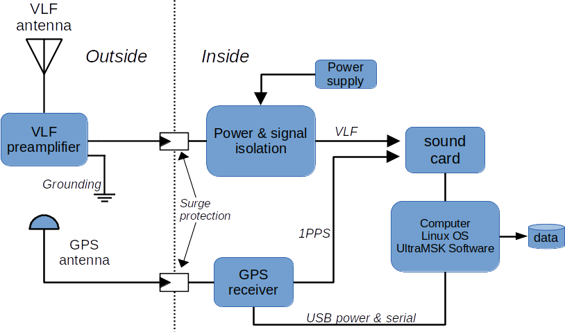
A typical UltraMSK hardware setup will consist of a VLF antenna and preamplfier, a power supply for the preamplifier and a GPS receiver with a 1PPS signal output. A computer & sound card is needed to run the UltraMSK software.
Installing Linux
UltraMSK runs on the Linux operating system. Install Linux on your computer. Most of the main Linux distributions are suitable such as Rocky Linux, Debian or Ubuntu etc. UltraMSK will also run on Raspberry PI computers.


![]()
Sound card connections
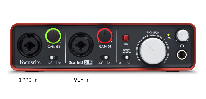
Once you have your PC setup and running CentOS, the next task is to setup the inputs to the soundcard. Typically, the GPS 1PPS signal connects to the left or first input channel and the VLF signal can be connected to the right or second channel. If you have a multichannel soundcard then connect any additional VLF signals to the subsequent input channels of the computer sound card.
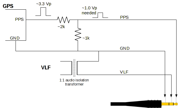
It is important that the GPS 1PPS signal does not overload the soundcard input. The ideal level for the 1PPS pulse is around 50 % of the full scale input level. You may need to attenuate the 1PPS signal and isolate the VLF signal for best results.
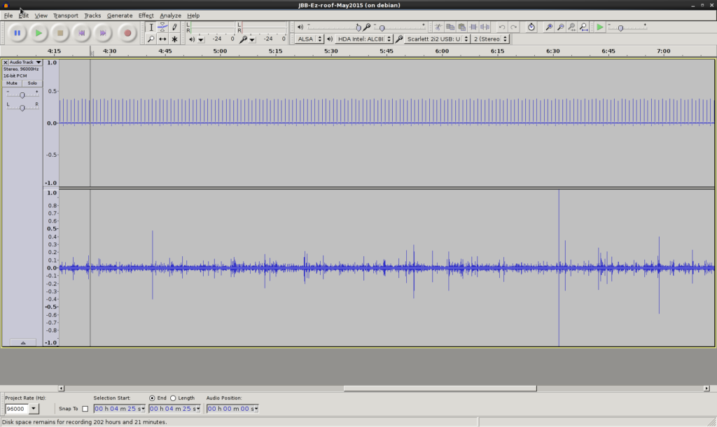
Signal check
Once you have the GPS 1PPS and VLF signals connected to the sound card, use a sound recorder such as Audacity to check the connections and signal quality are OK. The 1PPS pulse height needs to be around 50 % of the full scale range but it must be above 25 % full scale and without any clipping of the pulse waveform. Setting up the 1PPS signal is one of the most important steps in the configuration of your UltraMSK receiver. It is critical that the 1PPS pulse is correctly detected for the receiver to function optimally. Depending on soundcard, you may be able to use the ‘alsamixer’ command to adjust the gain of the 1PPS channel. The VLF signal level should be adjusted to make good use of the available dynamic range but without clipping too many lightning sferics.
Software Installation
Download the latest (May 2022) build of the ultramsk software:
- For Debian/Ubuntu: UltraMSK-1.3.0.tar.gz UltraMSK-1.2.2.tar.gz
- For CentOS/RedHat: UltraMSK-1.3.0-el9.tar.gz UltraMSK-1.2.2-el7.tar.gz
- Other versions available for various systems. Please contact us.
A license is required to run the software. A free evaluation license is available. Please contact us to discuss your requirements.
UltraMSK options
Running msk as shown below will display a list of command line options.
[james@orchid tmp]$ tar -zxvf UltraMSK-1.1.5.tar.gz
UltraMSK-1.1.5/
UltraMSK-1.1.5/msk
UltraMSK-1.1.5/misc/
UltraMSK-1.1.5/misc/vtcard
UltraMSK-1.1.5/startUltraMSK.sh
[james@orchid tmp]$ cd UltraMSK-1.1.5/
[james@orchid UltraMSK-1.1.5]$ ./msk
UltraMSK. Version 1.1.5. Build Nov 30 2018.
Copyright 2005-2018 UltraMSK.com (info@ultramsk.com)
Receiver options:
-f [frequency] : set receiver Frequency (Hz)
-b [baud rate] : set MSK baud rate. Use 0 for CW. (default = 200 Hz)
-c [call sign] : set station Call sign (default = MSK)
-r [resolution] : set output Resolution (default = 1.0 seconds)
-o [directory] : set data file Output directory (default = .)
-g [gain] : set 1 PPS signal Gain (default = 1.0)
Audio sampling options:
-p [input] : set input channel for 1 PPS signal (default = 1)
-s [input] : set input channel for VLF Signal (default = 2)
-D [device] : enable ALSA sampling using specified device
-F [sample rate]: set ALSA sampling rate (default = 96000 Hz)
-V [buffer] : enable vlfrx-tools sampling
Output options:
-d : enable status output
-l : enable combined polar output (dB, degrees)
-m : output messages to a log file
-i : enable binary file format output
-h [site name] : specify the site name to appear in the output file
-L [file prefix] : output one minute summary file
Wideband output options (licensed feature):
-W [resolution/s] : enable wideband power spectrum output
-U [frequency/Hz] : set wideband power spectrum upper output frequency
-X [file prefix] : set wideband output file prefix (default = UWB)
Advanced options:
-t [time/ms] : set 1 PPS window (default = 0.950 ms)
-B [time/s] : set sampling buffer length (default = 1 s)
-R : Enable real-time scheduling
[james@orchid UltraMSK-1.1.5]$
Your UltraMSK license file
Once you have received your license.dat.gz file, uncompress it and copy it into the UltraMSK directory.
[james@orchid tmp]$ mv license.dat.gz UltraMSK-1.1.5
[james@orchid tmp]$ cd UltraMSK-1.1.5/
[james@orchid UltraMSK-1.1.5]$ gunzip license.dat.gz
[james@orchid UltraMSK-1.1.5]$ more license.dat
Name: James Brundell
Organization: UltraMSK.com
License: Evaluation
Options: ARM WIDEBAND
Expires: 2022-12-31
Key: A91D1C7A1F….
Running UltraMSK
Use the startUltraMSK.sh to run the software. The script will start the vlfrx-tools sound card sampler and then start one msk receiver process for each VLF station received. You will need to edit the script to specify the name of the sound card device and to setup which VLF stations to receive. Also check that your user id is a member of the ‘audio’ group for access to the sound card devices.
Checking the GPS 1PPS signal
To get good phase data it is important to check the the GPS 1PPS detection is working correctly. Use the -d option to display some additional 1PPS timing information.
[james@orchid2 ultra]$ ./msk -d -f 19800 -c test [... your particular sampling options...]
...
1651787023.122 95997.976115 -2.10821e-05 1 -0.999983
1651787024.123 95997.976446 4.01467e-08 1 -0.999985
1651787025.124 95997.976347 2.6899e-08 1 -0.999987
1651787026.125 95997.976577 5.40165e-08 1 -0.999985
1651787027.126 95997.976644 6.04856e-08 1 -0.999986
1651787028.041 95997.976854 8.41245e-08 1 -0.999985
1651787029.126 95997.976681 6.0663e-08 1 -0.999988
1651787030.042 95997.977099 1.09392e-07 1 -0.999987
^C% Terminating…
Terminate using Ctrl-C. For each GPS pulse received the program outputs one line of 5 numbers. The first number is the unix time stamp of the pulse. The second number is the current estimate of sound card sampling rate. This should be stable to 3 or 4 decimal places. The third number is the time difference in seconds between an internally generated 1 Hz signal and the received GPS 1PPS signal. This should be close to the accuracy of the GPS receiver’s 1PPS timing signal. The fourth number is the number of seconds since the previous GPS pulse was received. This should be 1 if each 1PPS is being detected. The fifth number is the correlation coefficient of a linear fit to the phase of the GPS pulse versus frequency. This value should be very close or equal to -1.0. If not check that the 1PPS signal level is OK.
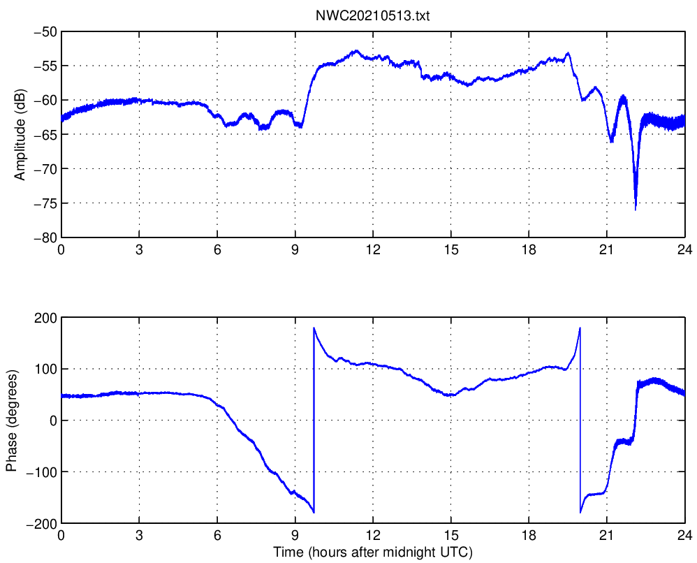
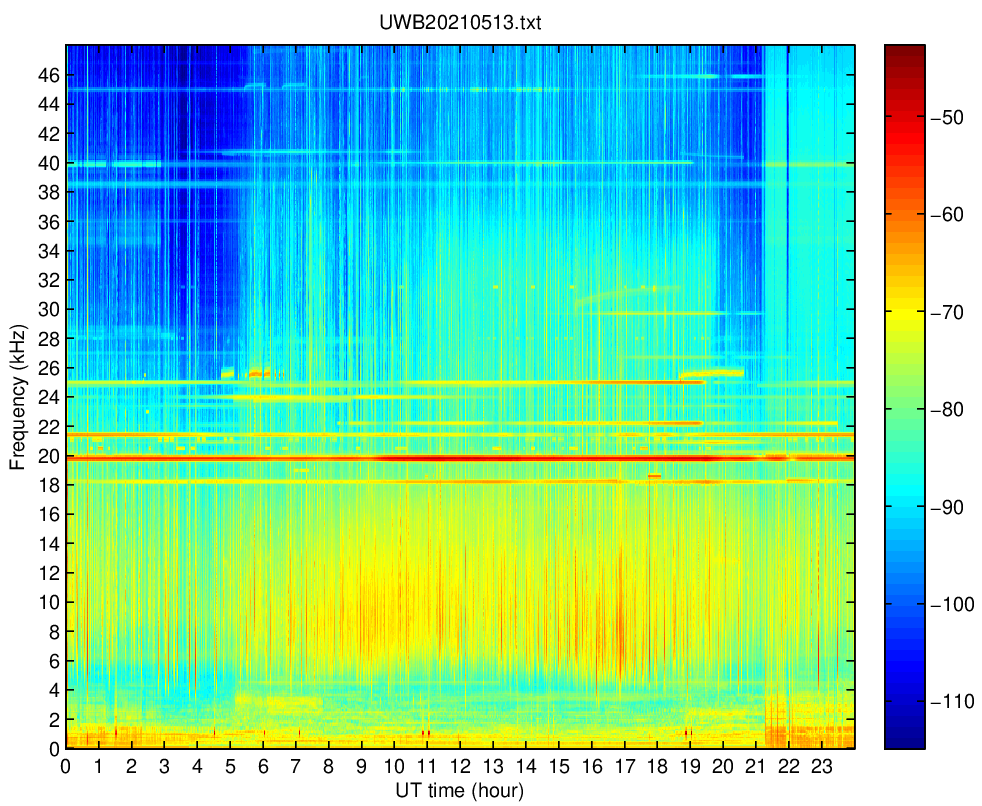
Data Plotting
Two MatLab scripts are provided. plotUltraMSK.m for plotting the amplitude and phase data and plotUltraWideband.m for plotting the optional wideband data.
Final Configuration Steps
To ensure that your receiver starts automatically whenever the you computer reboots, add the start script to your crontab entry. Use NTP or chronyd to keep your computer clock accurately synced. This will ensure that your data files are accurately time stamped.
Archived information
Some more information is available in the previous installation instructions for Fedora 17
Stuck? Feel free to ask for help at any stage!