This section contains information about VLF radio receiver hardware designs suitable for use with the UltraMSK software. Please note that I am unable to supply finished hardware at this stage.
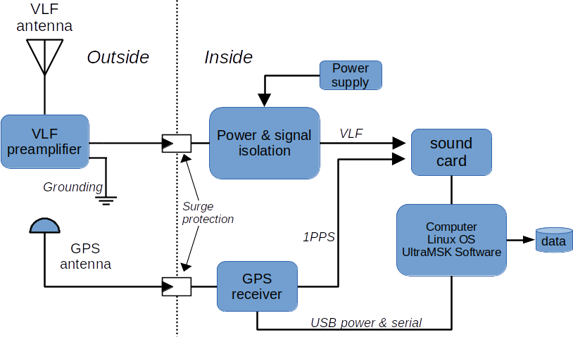
System Overview
A typical UltraMSK hardware setup will consist of a VLF antenna and preamplifier, an isolated power supply for the preamplifier and a GPS receiver with a 1PPS signal output. A computer & sound card is needed to run the UltraMSK software.
A VLF Electric Field Antenna System
The VLF electric field antenna system consists of the preamplifier unit, an aerial element and antenna hardware. The design details for the entire system are outlined below.

E-field VLF Preamplifier
The preamplifier contains filters, amplification and a balanced signal output suitable for driving long cable runs.

The complete schematic features:
- GDT input protection
- TVS diode protection for output & power input
- AD744 amplifier
- DRV134 Balanced line driver output. Alternatively, SSM2142 can be used if available.
- +/- 12 V DC input power required

Some additional notes. Capacitors types as follows:
- C2, C12, C13: 10 pF ceramic disc NPO
- C11: 100 pF ceramic disc NPO
- C3, C4, C5 & C6: 100 nF monolithic bypass capacitors
- C1: 10 nF MKT polyster
- C7, C8, C9, C10: 35 Vdc tantalum
Resistor values: R2 can be varied from 1 to 10 mega-ohms depending on desired low frequency response.
Preamp CAD files
Eagle CAD files for the preamplifier schematic and PCB can be downloaded from here.
Complete preamplifier unit
The preamplifier unit must be mounted outside at the base of the antenna. A waterproof enclosure is required. The enclosure needs to have a temperature rating that matches the expected environmental range. Polycarbonate plastic enclosures are typical rated for service from -40 degC to +120 degC.
- IP65 rated enclosure. e.g. digikey 377-1881-ND
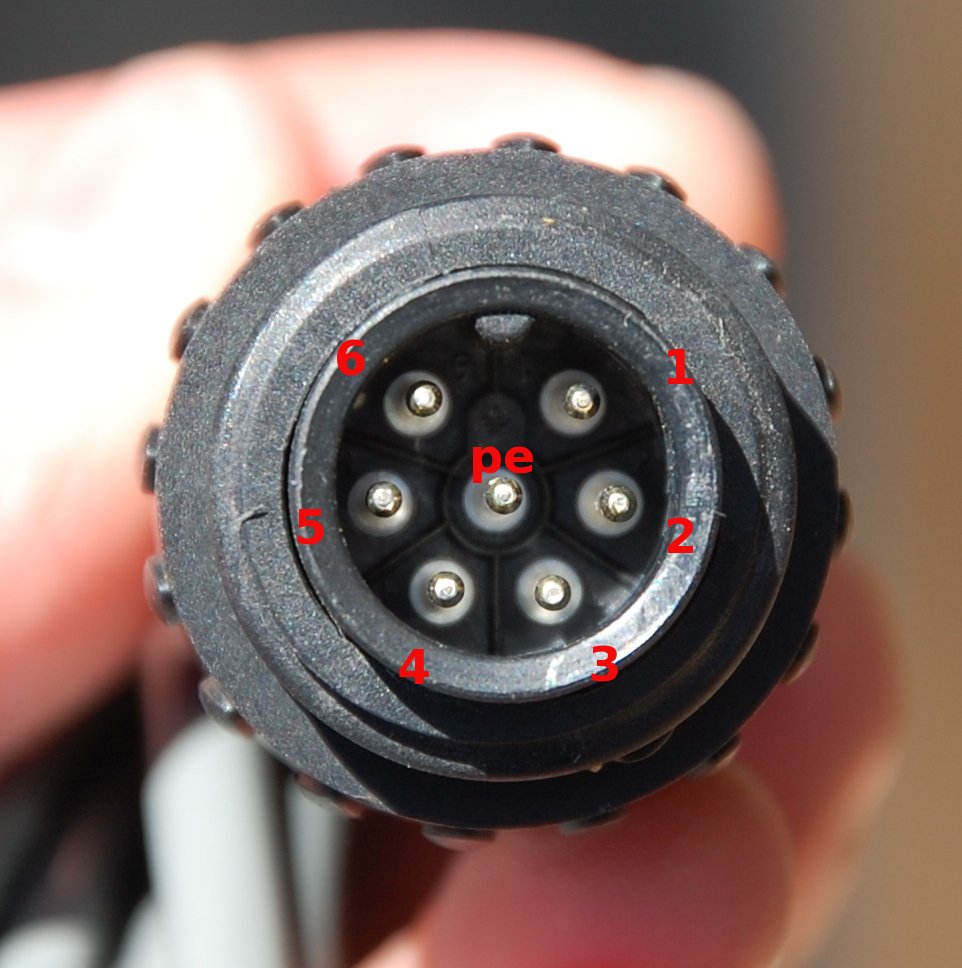
- Output connector 7 pin ecomate. e.g. digikey 361-1082-ND
- The preamplifier unit MUST be earthed via the threaded earthing lug

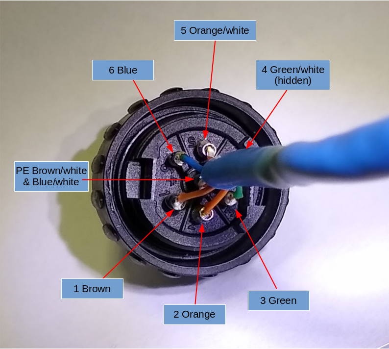
Suggested pin out for the Amphenol Ecomate connector:
The center PE pin on the ecomate connector engages first. Use this for the 0 V GND connection. The VLF output signal is a balanced output requiring a 2 wire connection. Pins 3 & 4 can be left unconnected or used for additional ground connections. Alternatively they could be used for a secondary VLF signal output. If using Cat 5/6 cable then a suggestion is to use the brown pair for +12 and GND, the blue pair for -12 V and Gnd, and the green and orange pairs for VLF signals.
| Pin number | Signal description | Suggested Cat 5/6 wire |
|---|---|---|
| 1 | +12 V DC input power | Brown |
| 2 | + VLF balanced signal output | Orange |
| 3 | GND or additional +VLF signal line or NC | Green |
| 4 | GND or additional -VLF signal line or NC | Green/white |
| 5 | – VLF balanced signal output | Orange/white |
| 6 | -12 V DC input power | Blue |
| PE | GND | Brown/white and Blue/white |
The E-field antenna hardware
The following hardware is required to construct the complete antenna system:
- 1 metre length of 40 mm PVC pipe
- plastic end cap to cover the top of the pipe
- expanded rubber pipe insulation size to fit snugly inside the PVC pipe
- length of 40 mm x 40 mm x 3 mm aluminium equal angle extrusion
- 2 stainless steel hose clamps
- stainless steel bolts to attached the preamplifier unit to the aluminium
- Wire or coaxial cable and a BNC plug to construct the aerial element

The aerial element for the electric field signal
The aerial element can be constructed from RG-58 coax and a BNC connector. The length is not critical. Match the length of the upper section to the length of the PVC pipe. Add on an additional length to reach the preamp. Keep the length of coax, from the BNC to the point where the outer braid is cut, as short as possible.
An alternative aerial option would be to use a commercial CB whip style antenna. Locate the VLF pre-amplifier at the base of the antenna. Connect the preamp to the antenna via the shortest length of coax practical.

Antenna installation
The antenna needs to be installed in high position such as the roof of a building or on a mast. On roof tops, the VLF electric field is usually much larger at an edge or near a corner than in the center of a flat roof. Keep away from other electrical equipment such as heating, ventilation and air conditioning (HVAC) units as these can generate a lot of noise at VLF. The antenna must not be under or even close to other conductors, not even trees, which are grounded at VLF and so tend to short out the VLF electric field.
Our handheld portable VLF receiver is ideal for conducting site surveys before installing your antenna. See https://www.ultramsk.com/a-portable-vlf-preamplifier/

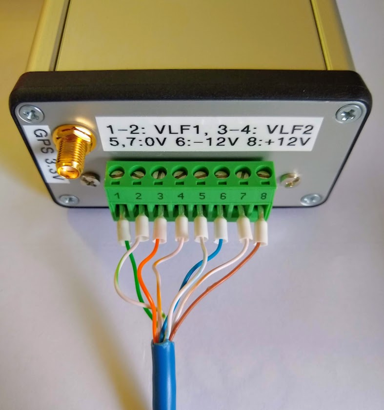
Preamp Power Supply and GPS receiver
This unit receives the balanced VLF radio signals from up to 2 preamplifiers via 1:1 isolation transformers. A DC/DC converter generates an isolated +/- 12 V DC power supply from the USB input power. A GPS receiver generates a 1PPS signal.


PSU and GPS schematics
Schematics for the VLF power supply board
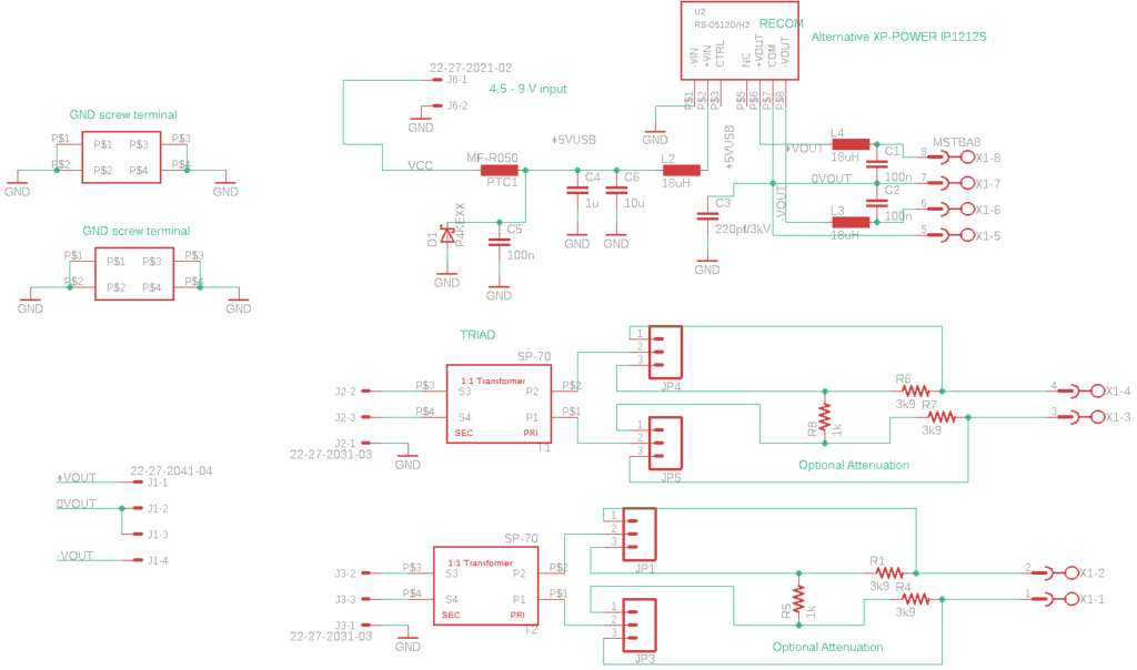
and GPS board. 2025 update: The GPS-11058 module from SparkFun is no longer available. An alternative module is available: https://www.ultramsk.com/2025/11/19/low-cost-gnss-module-with-1pps-output-signal/

Eagle CAD files and end panel design
Eagle CAD files for the power supply and GPS boards can be downloaded from here.
Design for the end panels:
Internals
The PCBs fit inside the enclosure slots. Signals are wired from the molex connectors to the front mounted panel connectors.

Jumpers on the power supply board can be used to adjust the VLF signal level.

FTDI serial cable
This FTDI serial cable can be used to configure and monitor the serial data from the GPS receiver. Connect the 3.5 mm ‘audio’ jack end of the cable to the “Serial” output on the power supply unit. Connect the USB end to a free USB port on your computer.

Computer sound card connection and signal check
Connect the 1PPS signal to the first input channel and the VLF signal to the second input channel of the computer sound card.

Finally, use a sound recorder such as Audacity to check the connections and signal quality are OK.
